IDaP+ CORNET 369 EN

Final results · 2023–2026

Integrated Data‑based Process Chain Optimisation+

Casting, heat treatment and machining, controlled as one chain instead of three separate processes.

IDaP+ investigated where residual stress and distortion actually enter an aluminium stator housing on its way from the sand mould to the finished bore – and how that information can be measured, simulated and passed on between the companies that carry out each step.

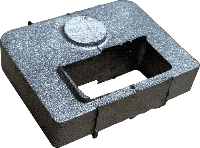
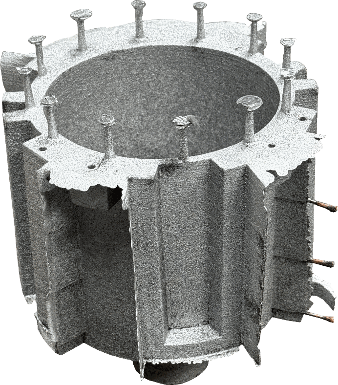
Sectioned aluminium stator housing in the as-cast condition, cast from EN AC-42100 in a 3D-printed sand mould.
Project workpiece · stator housing, as cast
Programme
CORNET, 34th callNational reference 369 EN (DE)
Duration
01.09.2023 – 31.05.2026Extended at no additional cost
Consortium
5 institutes · 2 countriesGermany and Austria
Material & part
EN AC‑42100 (AlSi7Mg0.3)Stator housing, ⌀ 177 mm × 209 mm
Status
CompletedContinued in IDaP+ II
The project

Every manufacturing step hands the next one a disturbance it cannot see

The chain of aluminium casting, heat treatment and machining supplies the structural components of electric drives, scroll compressors and battery housings – parts with the highest demands on dimensional accuracy. Every step in that chain generates residual stresses and geometric deviations that act as an uncontrolled disturbance variable in the next one.

In industry these steps are usually carried out by different companies. Data generated at one point, which would be a valuable control variable further downstream, are not passed on: interfaces are missing, and data sovereignty concerns and proprietary cloud platforms stand in the way. Each actor therefore controls its process on incomplete knowledge of what came before – which systematically produces scrap, iteration loops during ramp-up and forfeited efficiency.

IDaP+ set out to develop and validate a continuous, data-based control strategy for the complete chain: experimental characterisation of all sub-processes, linked simulation models, sensor-based measurement concepts for the machining operations, and a data exchange concept that works without a central database.

The work was carried out as an international collective research project of two research associations and five research institutions in Germany and Austria, with a project-accompanying committee of 46 companies from every stage of the chain – foundries, mould makers, heat treaters, tool manufacturers, measuring equipment and software providers, contract manufacturers and OEMs.

Process chain

A physical chain, a digital one underneath, and the loops between them

The project traced a single component from the sand mould to the measured bore and asked, at each transition, which information the next step actually needs – and how it could reach that step across company boundaries.

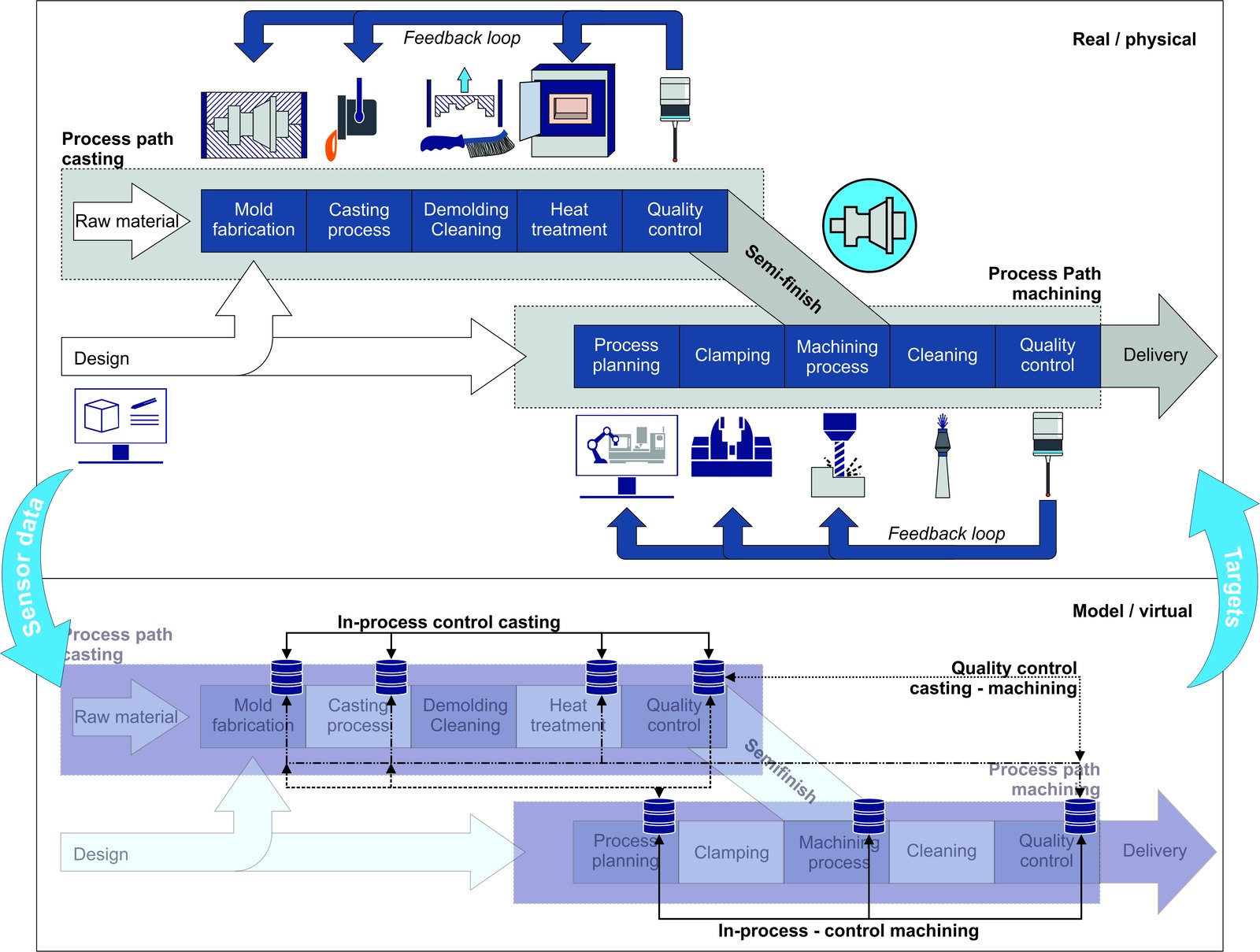
Diagram of the IDaP+ process chain: the physical chain of casting, heat treatment and machining above, its digital representation below, linked by sensor data and target values and closed by feedback loops within each path and across the chain.
The control concept of the project. Above, the physical chain from raw material to delivery, with a feedback loop inside the casting path and inside the machining path. Below, its digital representation, in which the recorded and simulated states of every step are held. Sensor data run downwards, target values run back upwards, and the quality control of one path becomes an input to the other.
Project activities

What was designed, cast, measured, machined and modelled

Thirty-three months of work across five institutes in two countries, carried out on one shared workpiece so that every stage of the chain could be observed on the same part.

Specification

A workpiece designed to make the whole chain visible

A stator housing for an electric motor was chosen together with the User Committee and then redesigned for the project: the geometry carries the stator bore, the deep holes and the threads of all partners on one part, and its wall-thickness steps and interrupted flange ribs are placed where they provoke the effects the project set out to observe.

Two simplified geometries were derived alongside it. Stepped plates with three wall thicknesses serve the calibration of mould and quenching models and the orthogonal cutting trials; a stress lattice with deliberately unequal bar cross-sections provides an analogy part on which residual stress can be measured with the hole-drilling method and by diffraction.
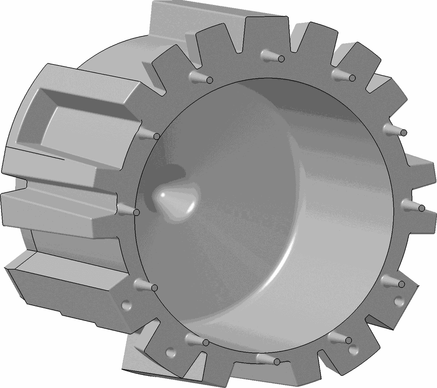
CAD model of the stator housing geometry designed for the project.
The project workpiece, designed so that every partner’s machining operation fits on one part.

Casting

Moulds printed, parts cast, temperatures recorded from the inside

All experimental geometries were cast at the utg in additively manufactured, furan-resin-bonded sand moulds, with ceramic filters, sand cores and chills placed according to a design of experiments. The stress lattices were poured in gravity casting, the stator housings in low-pressure die casting on a furnace that was rebuilt during the project.

Thermocouples cast into the parts recorded the temperature history of every pour, synchronised with the mould filling pressure. These curves became the calibration basis for the casting simulation and later for the quenching model, and they were shared with all partners in a common format.

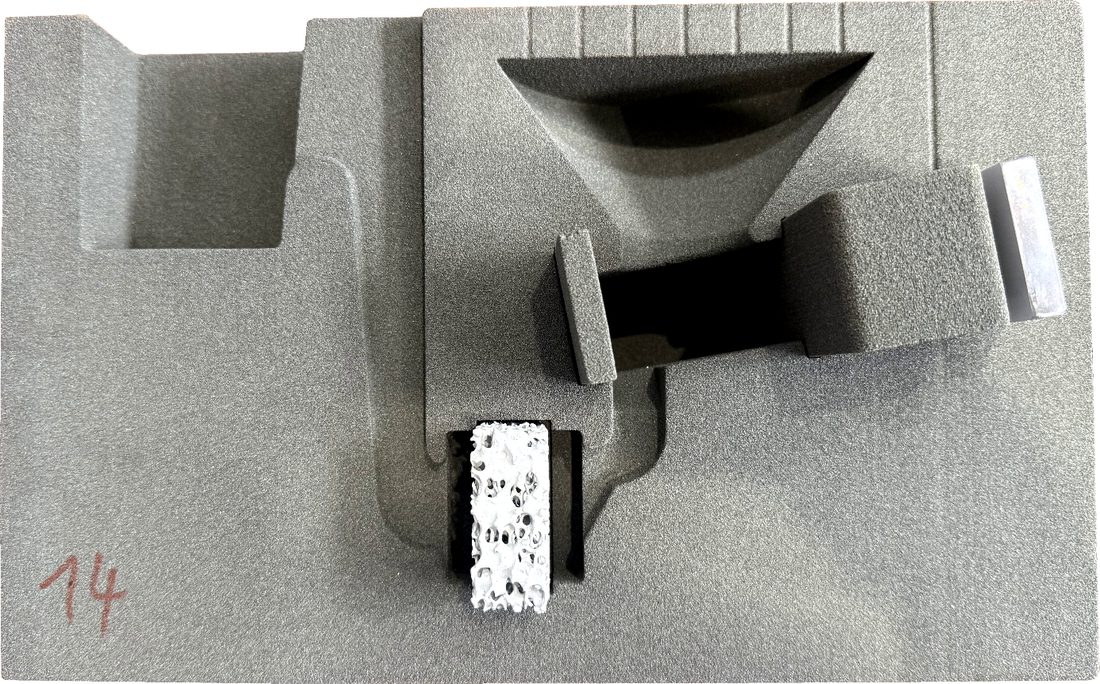
Opened 3D-printed sand mould for the stress lattice with the ceramic filter and the inserted sand cores.
Printed sand mould for the stress lattice, with filter, cores and a chill at the thin bar.

Casting · sensor development

A sensor that watches the melt enter the mould

Thermocouples say when metal arrives, but not how fast. A melt volume flow sensor based on Lorentz force velocimetry was therefore developed for the low-pressure casting process: magnet assembly, force measurement and thermal protection were designed and built at the utg, referenced against a laser distance sensor above the riser tube, and then installed in the furnace for the casting of a complete stator housing.

The sensor makes the filling of a part observable while it happens. It supports the validation of mould filling simulations, and in production it opens a route to monitoring: a clogged slot nozzle or a contaminated riser tube changes the signal before it changes the part.

Assembled melt volume flow sensor with magnet carrier and force measurement.
The assembled melt volume flow sensor before installation.
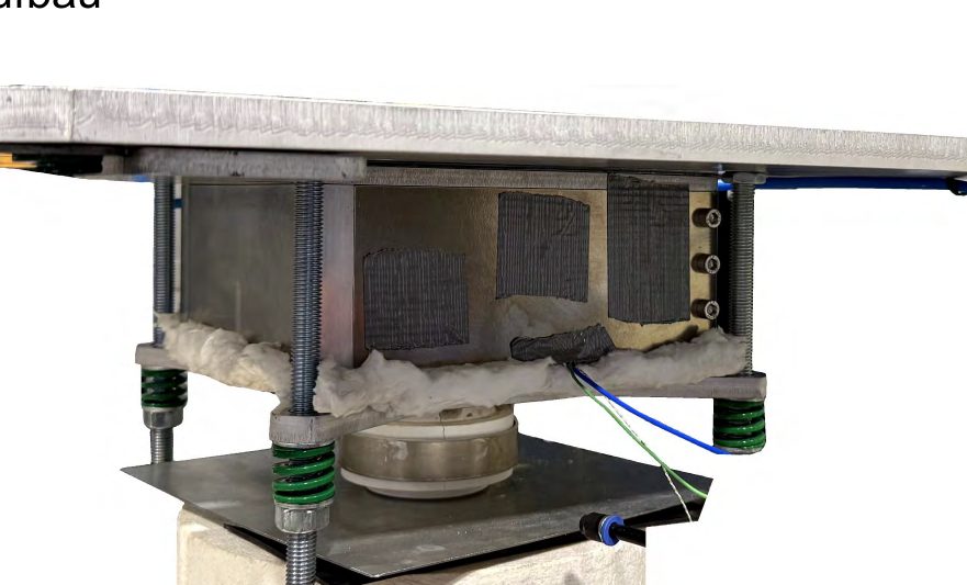
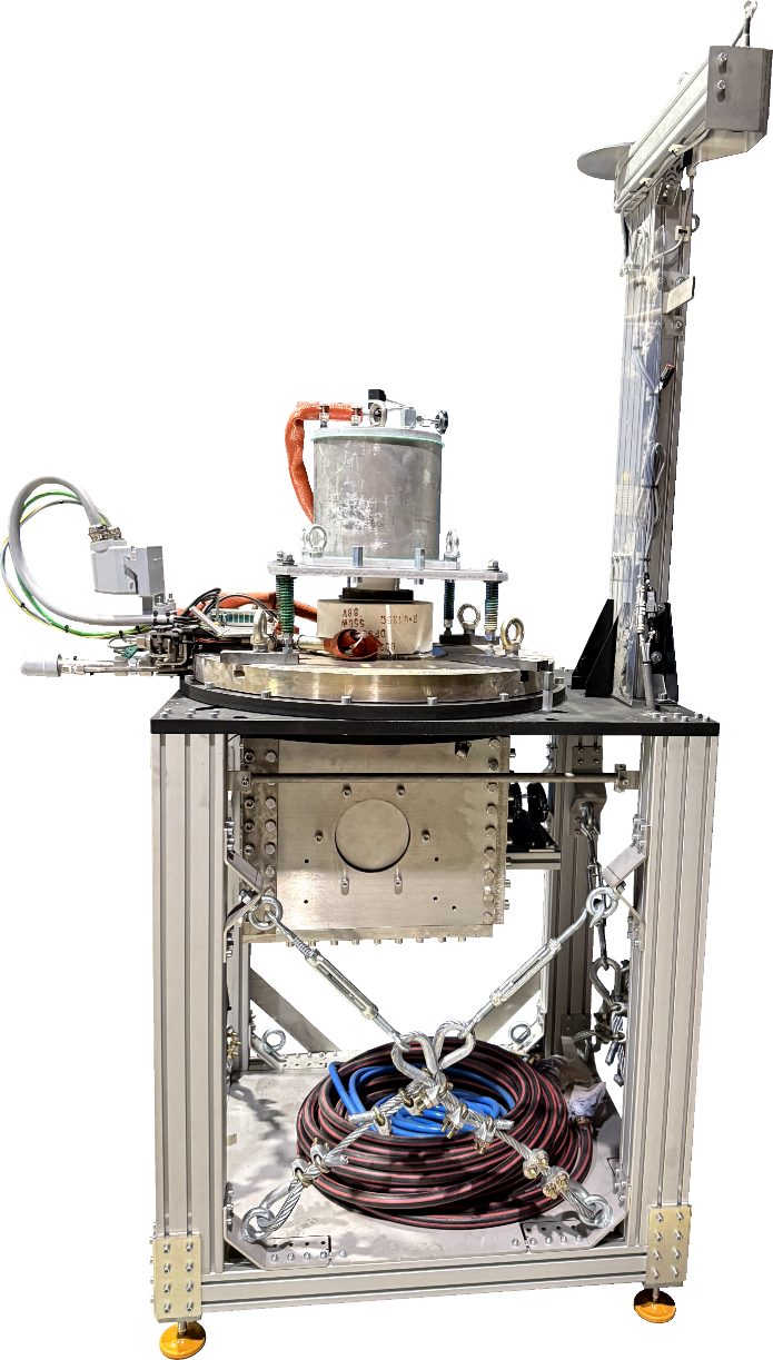
Newly built low-pressure casting furnace used to cast the stator housings.
The low-pressure casting furnace rebuilt for the project, with the sensor seat in the riser tube.

Casting · metrology

Every cast part digitised, and the mould corrected from the scan

The castings were measured with a structured-light 3D scanner on a rotary-tilting table and compared against the nominal geometry at defined points of interest. On that basis a deviation compensation program was adapted for cast parts: instead of scaling the pattern by a single shrinkage factor, individual nodes of the target mesh are displaced locally, and a corrected sand mould is printed from the result.

The loop was closed once within the project – a compensated stress lattice was designed, moulded and cast – and the scatter analysis that goes with it shows how casting dimensions can be placed inside a given tolerance window rather than merely near it.

Cast aluminium stress lattice, the asymmetric analogy geometry used in the project.
The stress lattice: unequal bar cross-sections produce a measurable stress profile.

Casting · heat treatment

Locating where the residual stress enters the part

The stress lattice was designed for exactly this question. Residual stress was measured on it after casting by the hole-drilling method, then again after heat treatment, and the casting process was modelled in parallel so that measurement and simulation could be read against each other.

After sand casting the measured values stayed within the uncertainty of the method – for these dimensions the part leaves the mould essentially unstressed. The stress state that machining later releases is introduced by the quenching step. That is where the project concentrated its modelling and control effort from then on.

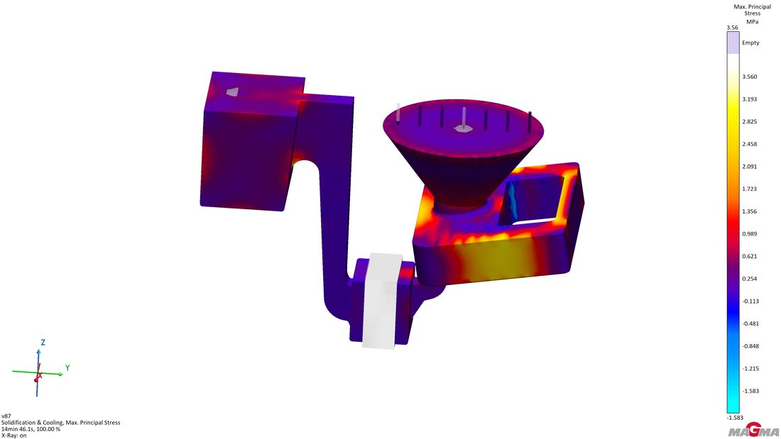
Casting simulation of the stress lattice showing the maximum principal stress after solidification and cooling.
Casting simulation of the stress lattice, maximum principal stress after solidification.

Heat treatment

Quenching turned into a controlled, repeatable experiment

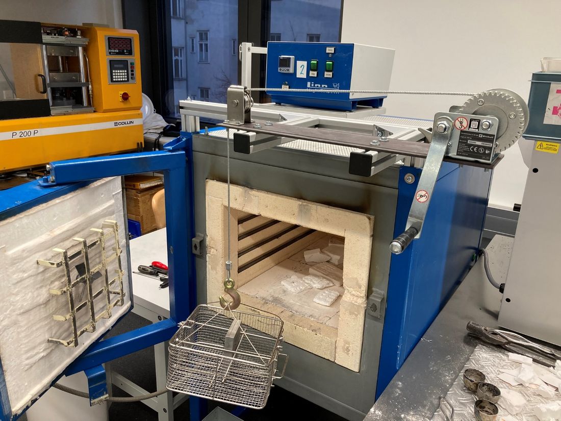
A quenching device with a cable winch was built so that parts leave the solution annealing furnace and enter the water bath at a defined speed and in a defined orientation. Two extreme cases were run through the whole chain: the thin side of the part immersed first, and the thick side first.

Cast-in thermocouples recorded the cooling curves at several positions for each variant. These curves are what made the quenching step describable at all – on the simple stepped plate first, and afterwards on the far more complex stress lattice.

Solution annealing furnace with the quenching device and cable winch used to lower the components into the water bath.
Furnace and quenching device: the immersion direction it sets is a control variable, not an accident.

Heat treatment · materials

The alloy characterised for the conditions it really sees

Flow curves for both alloys were recorded in the dilatometer along the temperature path of the quench, and a full artificial ageing series was run, from short holds to a full day, with every specimen tested in compression afterwards. The series established the ageing time that all later parts in the project were given.

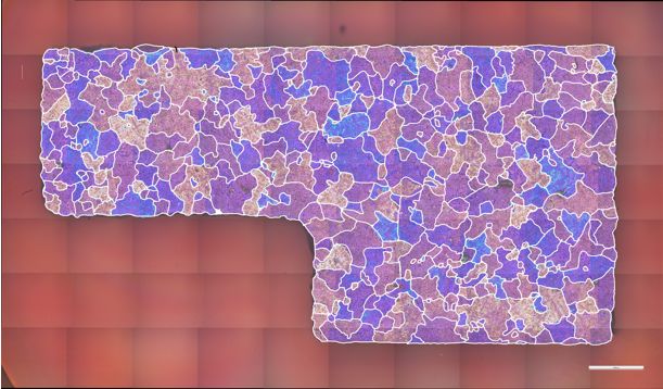
The cast structure was characterised metallographically at defined sampling positions, with Barker etching under polarised light for the grain size. The coarse grain of the cast alloy is also the reason a finer-grained wrought alloy with the same precipitation sequence was added to the programme, so that the diffraction measurements had a reliable reference.

Barker-etched micrograph of the cast structure under polarised light, with the individual grains outlined.
Barker etching of the stepped plate, grains outlined for the grain size evaluation.

Heat treatment · simulation

A quenching simulation built from measured cooling curves

The heat transfer between part and water was described as a function of the component surface temperature, following the approach of Bamberger and Prinz and extended in the low temperature range, and then calibrated against the measured cooling curves of the stepped plate. Carried over to the stress lattice, the model reproduced the measured curves for both immersion directions.

Coupled with the dilatometer flow curves, this gives a chain of Transient Thermal into Static Structural analysis that predicts the residual stress state a part carries out of the heat treatment – the input the machining side had been missing.

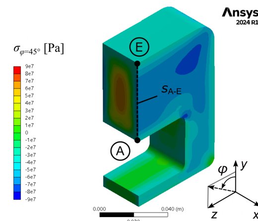
Finite element result of the quenching simulation showing the residual stress component in the stress lattice at room temperature.
Simulated residual stress in the stress lattice at room temperature after quenching.

Heat treatment · metrology

Residual stresses mapped by diffraction

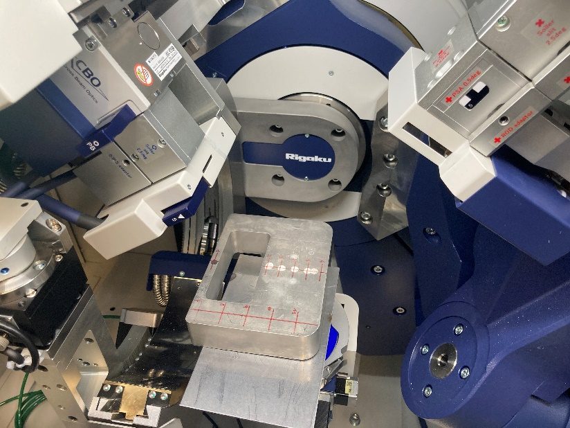
The surface stresses of the quenched stress lattices were mapped on the large-chamber diffractometer of the X-Ray Center at TU Wien, in two stress directions and along defined paths across the part, for both immersion directions and after artificial ageing. Depth information was added by removing material electrochemically in small steps between measurements.

These maps are the counterpart to the simulation: the same quantity, on the same part, measured independently. Beyond the laboratory scale, a beam-time proposal for neutron diffraction was prepared to reach the stress state inside the component wall.

Stress lattice mounted in the large-chamber diffractometer of the X-Ray Center at TU Wien.
Stress lattice in the large-chamber diffractometer at TU Wien.

Machining

Orthogonal cutting at production speeds, in both material conditions

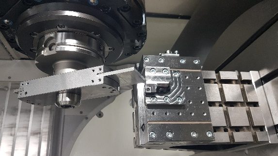
To compare the as-cast and the T6 condition under clean, model-ready conditions, a strictly orthogonal cut was realised on a five-axis machining centre programmed to emulate a turning operation: the workpiece disc runs in the spindle, a single polycrystalline diamond edge sits on a dynamometer on the machine table, and the spindle speed is adjusted continuously so that the cutting velocity stays constant as the contact diameter shrinks.

The trials were run as a full factorial over the velocity and feed range typical of aluminium machining, for both material conditions. Forces, chip formation on high-speed video and the contact length between chip and rake face were recorded for every combination – the reference data set that the modelling work draws on.

Orthogonal cutting setup on the five-axis machining centre: workpiece disc in the spindle, single cutting edge on the dynamometer.
Orthogonal cutting realised on a machining centre, with the tool on a piezoelectric dynamometer.

Machining · materials

Material data taken at the strain rates of the cut

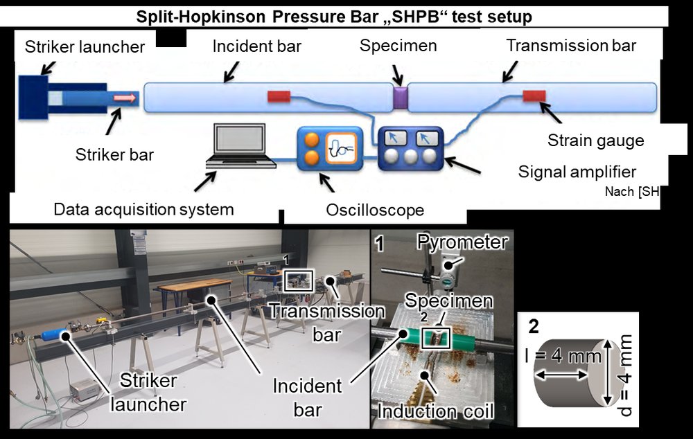
Cutting happens at strain rates a conventional testing machine cannot reach. The flow behaviour of both material conditions was therefore measured on a split-Hopkinson pressure bar with induction heating, so that strain rate and temperature could be varied independently across the range that occurs in the shear zone.

From these tests a Johnson-Cook parameter set was derived for the as-cast and for the T6 condition. The same parameters were then used by the partners in their machining models, which is what made the simulations along the chain comparable in the first place.

Split-Hopkinson pressure bar test setup with striker launcher, incident and transmission bars, induction coil and pyrometer.
Split-Hopkinson pressure bar with induction heating for high-strain-rate compression tests.

Machining · surface integrity

Reading the surface the cut leaves behind

Machining does not only release residual stress, it writes a new one into the surface layer. For every parameter combination the machined surfaces were measured by X-ray diffraction using the sin²ψ method, parallel and perpendicular to the cutting direction, for both material conditions.

To reach below the surface, material was removed from selected specimens by electrochemical etching in small steps, with a measurement after each step. The resulting depth profiles show how far into the part the mechanically affected zone reaches – the quantity a distortion model needs as its machining-side input, and one that is rarely available for aluminium cast alloys cut with sharp diamond tools.

Machining · simulation

Chip formation modelled from the ground up

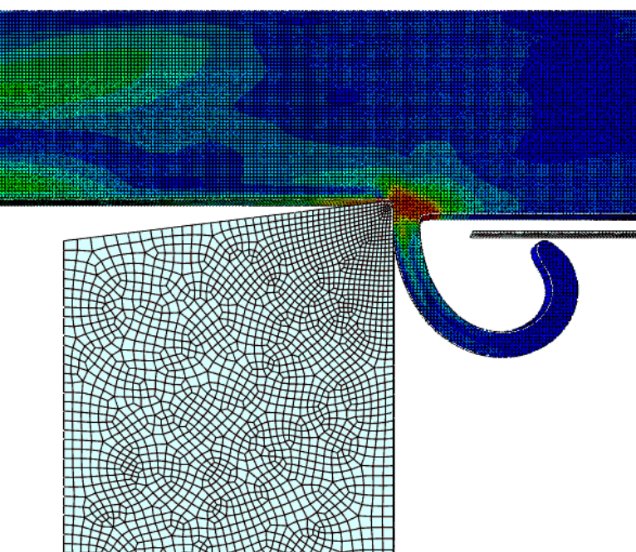
A coupled Eulerian-Lagrangian model of the orthogonal cut was set up in Abaqus, with the workpiece moving through an Eulerian domain so that the large plastic deformations of chip formation are handled without mesh distortion, the cutting edge as a rigid Lagrangian body in the experimental geometry, and a separating plate that keeps chip and workpiece from rejoining behind the edge.

The model runs with the project’s own Johnson-Cook parameters and reproduces the force trends and the chip shapes of the trials, including the higher force level of the heat-treated condition. It is the working basis on which the friction description is now being refined for the T6 condition, in the follow-up project.

Simulated chip formation from the coupled Eulerian-Lagrangian model, showing the curling chip and the deformation zone ahead of the cutting edge.
Simulated chip formation, shown for the fine and the coarse end of the parameter field.

Machining

Deep-hole drilling and tapping brought onto the real part

The deep holes were first developed on a simplified model with three bar cross-sections, then transferred to the stator housing itself. The trials ran on a machining centre under minimum quantity lubrication throughout, with thermography of the drilling operation, force and torque recording, and inspection of the finished bores.

In parallel, a finite element model of the process was built in which the two-fluted tool is represented by helical heat sources, validated on the simplified geometry against the measured temperature fields and then applied to the thin-walled and the thick-walled region of the housing. The material condition turned out to matter for process stability, which places the heat treatment ahead of the deep-hole operation in the sequence.

Machining · coatings

New cutting edge coatings deposited and put to work

High-entropy boride and carbide coatings were developed by physical vapour deposition and deposited on indexable inserts of an Austrian tool manufacturer – a low-temperature, gas-free process route chosen for its energy and environmental profile, and one that also opens the door to sensor functions on the tool surface.

The coated inserts were characterised and then run in cutting and milling trials against uncoated references, with the condition of the cutting edge documented before and after. The trials identified coating adhesion, rather than coating hardness, as the property to work on next.

Machining · tool development

A boring tool that measures what it is doing

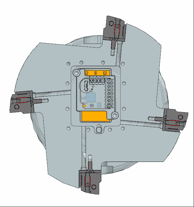
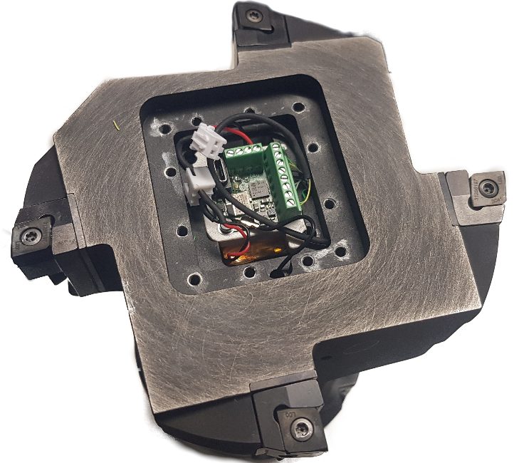
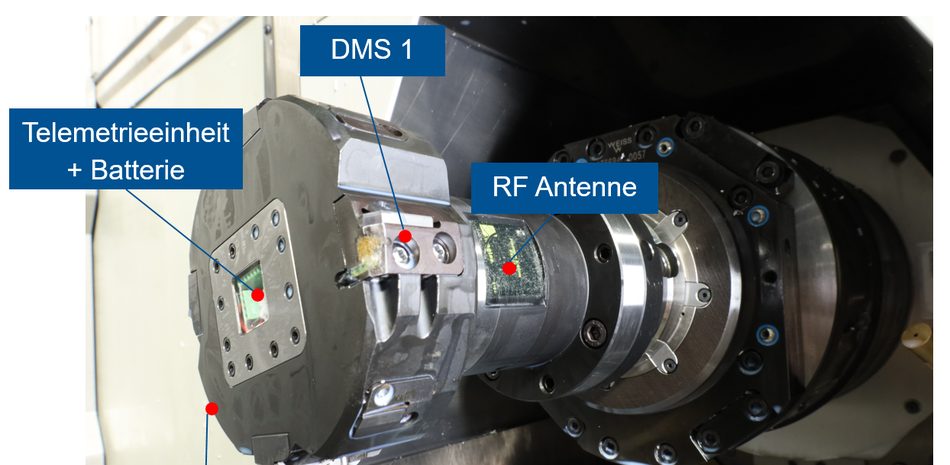
Together with a tool manufacturer, series-related precision boring tools for roughing and finishing were rebuilt into measuring instruments. Strain gauges sit in the tool body where the load path of the cutting edge passes through it; a telemetry unit with wireless transmission, an inertial measurement unit aligned with the axis of rotation and a rechargeable battery are housed in the tool itself – without giving up the internal coolant supply that aluminium machining depends on.

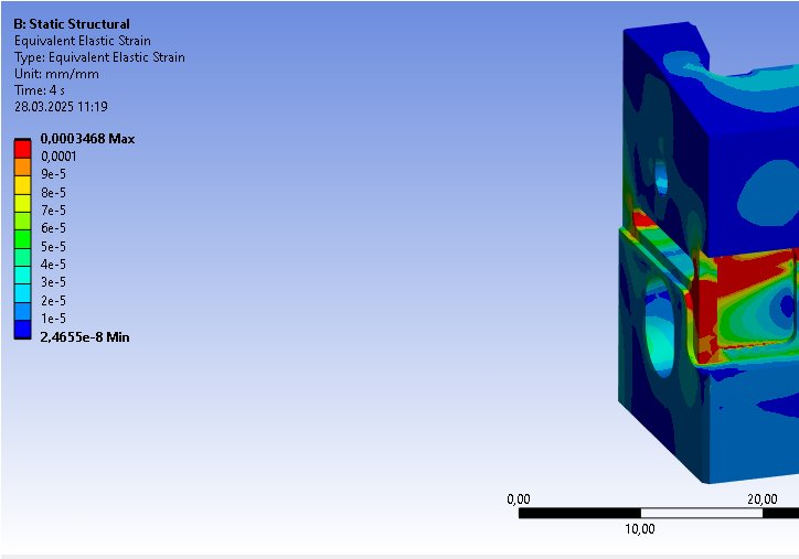
The positions of the gauges were worked out beforehand on a finite element model of the tool body, with the cutting, feed and passive force applied as separate load steps, so that each channel responds to the component it is meant to see.

Finite element model of the boring tool body under cutting load, used to place the strain gauges.
FE model of the tool body: the strain field decides where the gauges go.
Sectioned CAD model of the roughing tool showing the cavity for the telemetry module and battery.
Section through the roughing tool with the cavity for telemetry and battery.
Sensor-integrated precision boring tool with the telemetry module and battery visible in the tool body.
The built tool, telemetry module and battery between the adjustable cassettes.

Machining · tool development

Calibrated against reference equipment, then sent into the cut

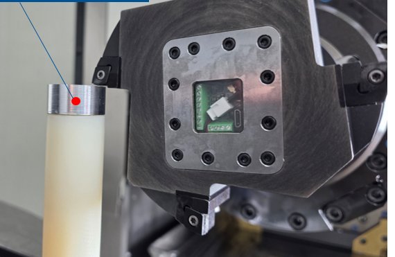
Before the tools could be trusted, each channel was calibrated on the machine against a reference dynamometer of known behaviour: a connecting element transfers a defined load into the cassette seats, the load is raised in steps, and the response of every strain gauge is recorded – for the roughing and the finishing tool separately.

The tools then went into analogy components before touching a project housing: turned aluminium rings that reproduce the bore of the stator housing, machined with the same tools and parameter sets. From there the work moved onto the cast housings themselves, in the HSK-100 spindle of the machining centre, with the acquisition triggered automatically from the NC program so that the recording starts and stops with the cut – the form the concept would take in series production.

Calibration of the sensor-integrated tool on the machine against a reference force transducer.
Calibration against a reference force transducer, load applied in steps.
Sensor-integrated finishing tool mounted in the HSK-100 spindle of the machining centre, with strain gauges, telemetry unit and antenna marked.
The tool in the HSK-100 spindle. DMS marks the strain gauge positions, alongside the telemetry unit with battery and the antenna.
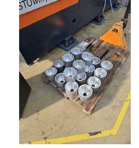
Turned aluminium analogy components used for the first machining trials with the sensor-integrated tools.
Analogy components that reproduce the stator bore, machined before the real housings.

Machining · workholding

A part that does not want to be held

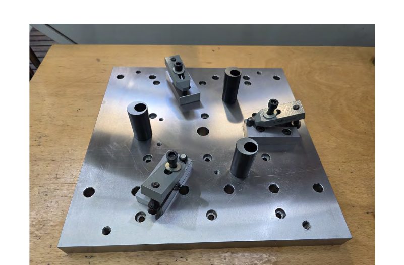
A thin-walled casting reacts to the way it is clamped, so the workholding became part of the experiment rather than an accessory to it. For the cast housings a fixture was built at the IfW: a base plate with spacer bushings that pick up the machined support faces and positioning bores, and clamping claws that hold the part for the boring passes.

Alongside it, the IFT used a fixture in two configurations whose part supports are instrumented with force sensors, so that the load the clamping actually applies is recorded together with the cutting data instead of being assumed. For the deep-hole drilling trials the ISF added a fixture with an adapter plate for the measuring equipment, a thermographic camera on the outer wall and eddy current sensors seated directly in the stator bore to follow its displacement during the cut.

On these setups the housings were prepared in a defined sequence – support faces, positioning bores and the bearing seat first, then the stator bore in roughing and finishing passes with the sensor-integrated tools, then the deep holes and threads.

Clamping fixture for the cast stator housings: base plate with spacer bushings and clamping claws.
The fixture for the cast housings, with spacer bushings and clamping claws on the base plate.
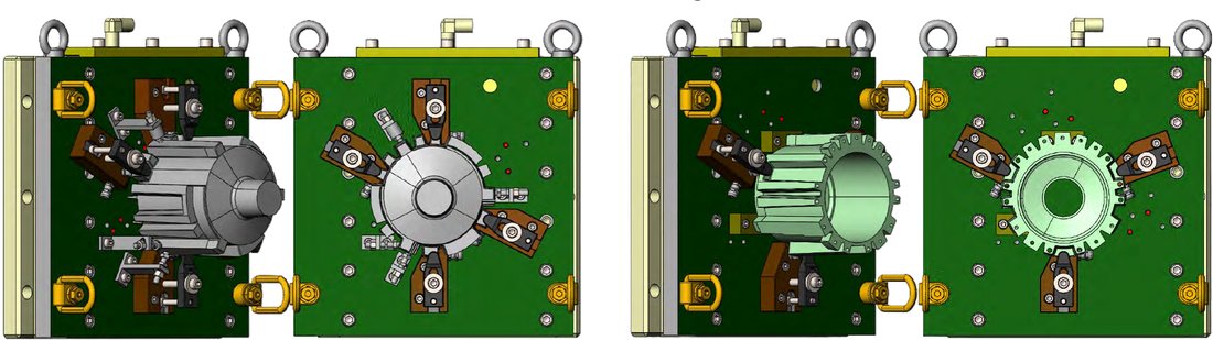
CAD model of the workholding fixture in two configurations, with the housing mounted and force sensors at the part supports.
The fixture in its two configurations, with force sensors at the part supports.

Machining · metrology

The finished housings measured twice – clamped, and released

Two housings that differed only in the immersion direction during quenching were run through an identical machining sequence with the same cutting parameters. The stator bore was then measured on a coordinate measuring machine in two states: with the part still in the fixture, and after unclamping. Roundness profiles were recorded at several heights in the bore and evaluated for diameter, roundness and cylindricity.

In the fixture the two parts are indistinguishable. They separate only on release, and in opposite directions – the part quenched with the thick side first holds its form, the other loses it. That is the experimental counterpart to the distortion simulation, and the reason an in-fixture measurement is only meaningful when the history of the part is known.

Data exchange

A data path that companies can actually use

The interface analysis in the project showed that a central project database would not transfer to industry, where the stages of the chain belong to different companies. The exchange was therefore built on Asset Administration Shells to the IDTA specification and implemented as a working demonstrator in Eclipse BaSyx.

The shell of a workpiece carries a traceability submodel whose references point at the casting, heat treatment and machining runs that this individual part passed through, addressable on the shop floor by QR code; the shell of a process carries its sensor, simulation and quality submodels. Data are referenced, not copied, so a machining company can release a quality result without releasing its process data. Since BaSyx derives an OPC UA address space from the same definition, no second mapping is needed for machine-level communication.

Energy & material efficiency

Where energy and material leave the chain

Each stage was examined for what it consumes. On the casting side the trials covered melt temperature, return material and gating design, and the melt flow sensor and the deviation compensation were assessed for what they contribute to avoiding scrap. On the heat treatment side the ageing series set how long the furnace really has to stay closed.

The machining trials ran under minimum quantity lubrication throughout, far below the consumption of flood lubrication, and the finite element models showed how the lubricant supply acts on the component temperature at the same time – so that optimising it addresses resource consumption and part quality together. The new tool coatings were developed with the same objective in mind.

Transfer

How the results reached industry

Transfer ran throughout the project rather than at the end: five committee meetings, bilateral trials with individual companies, conference papers, trade fairs and teaching.

Carried out during the project
Presentation at the student day of the IfW20.02.2024
SchnupperUni at TU Dortmund University14.08.2024
Open day of TU Dortmund University16.09.2024
Interview by the FQS on DGQplus, LinkedIn / XING04.10.2024
D/A/CH mechanical engineering conference20.11.2024
Paper at the WGP Annual Congress, Chemnitz02.–04.12.2024
Annual meeting of the Committee for Working Techniques (AfA)04.12.2024
Teaching Day, Faculty of Mechanical Engineering04.12.2024
45th A2LT plenary meeting25.09.2025
FEMS EUROMAT, Granada2025
Conference paper on residual stress analysis for aluminium cast alloys2025
Appearance at the EMO2025
Barbara Conference, Fraunhofer IGCV27.11.2025
Planned after the project
Presentation at the in-house exhibition of Wenzel25.06.2026
FQS webinar “Chilli Con Q”06.08.2026
Presentation at the CastForge trade fair20.–22.06.2028
Further publication in specialist journals and industry magazinesongoing
Adaptation of the lecture content of the participating institutesongoing
Partnership event to initiate follow-up activities with SMEswithin 1 year

Continued in IDaP+ II. The follow-up project takes up the two threads that IDaP+ left open: elaborating the Asset Administration Shell submodels for every sub-process, and closing the process chain control loop.

Participants

Research partners

The division of tasks between the two countries followed the process chain and was complementary rather than parallel – no partner could have covered this spectrum alone.

IfW

Institute for Machine Tools
University of Stuttgart · Germany

Technical and scientific management of the project. Boring of the stator bore, development of the sensor-integrated precision boring tools, machining simulation and the data exchange concept.

Head of instituteProf. Dr.-Ing. Hans-Christian Möhring
Project contactTim Reeber

ISF

Institute of Machining Technology
TU Dortmund University · Germany

Deep-hole drilling and tapping, flow stress characterisation on the split-Hopkinson pressure bar, chip formation and component-level FE modelling of the drilling process.

Head of instituteProf. Dr.-Ing. Dirk Biermann
Project contactMartin Sicking

utg

Chair of Metal Forming and Casting
Technical University of Munich · Germany

Casting of all experimental geometries in 3D-printed sand moulds, casting simulation, the melt volume flow sensor and the geometric deviation compensation.

Head of chairProf. Dr.-Ing. Wolfram Volk
Project contactGeorg Fuchs

IFT

Institute for Production Engineering and Photonic Technologies
TU Wien · Austria

Orthogonal cutting investigations, milling and clamping situation, machining distortion simulation along the chain, and the testing of new PVD tool coatings.

Head of instituteUniv.-Prof. Dipl.-Ing. Dr. techn. Friedrich Bleicher
Project contactsSeverin Maier · Matthias Thin

WWWT

Institute of Materials Science and Technology
TU Wien · Austria

The complete heat treatment path: quenching and ageing simulation, dilatometer flow curves, X-ray residual stress analysis, and the high-entropy boride and carbide coatings.

Head, Materials TechnologyUniv.-Prof. Dipl.-Ing. Ernst KozeschnikProject contact: Lukas Helml
Head, Materials ScienceUniv.-Prof. Paul MayrhoferProject contact: Alexander Kirnbauer

FQS

Forschungsgemeinschaft Qualität e.V.
Frankfurt am Main · Germany

Research association on the German side, representing the interests of the SMEs, coordinating the project and carrying the dissemination through the sector platform DGQplus.

ChairKlaus Schmieder
Project coordinationDr. Christian Kellermann-Langhagen

ASMET

ASMET Research GmbH – Austrian Society for Metallurgy and Materials
Leoben · Austria

Research association on the Austrian side, representing the Austrian SMEs in the project-accompanying committee.

ContactGerhard Hackl
Project-accompanying committee

46 companies steered the project

The committee covered every stage of the chain – foundries, mould and model makers, heat treatment operations, tool manufacturers, measuring equipment and software providers, contract manufacturers and OEMs – and ranged from SMEs to OEMs.

Germany 31

  • Apodis GmbH Salach
  • BCT Steuerungs- und DV-Systeme GmbH Dortmund
  • BMW AG Landshut
  • Breuckmann GmbH & Co. KG Heiligenhaus
  • Brinkhaus GmbH Isernhagen
  • Conbility GmbH Herzogenrath
  • EMG Casting AG Waldkraiburg
  • EMUGE-Werk Richard Glimpel GmbH & Co. KG Lauf
  • fabforce GmbH & Co. KG Netphen
  • Hermann Bilz GmbH & Co. KG Esslingen
  • HPM Technologie GmbH Dettingen an der Erms
  • ISBE GmbH Stuttgart
  • MAGMA Gießereitechnologie GmbH Aachen
  • MAPAL Dr. Kress KG Aalen
  • Mercedes-Benz AG Untertürkheim
  • Meshparts GmbH Stuttgart
  • ModuleWorks GmbH Aachen
  • Nemak Frankfurt am Main
  • Pfefferkorn GmbH & Co. Metallgießerei und Systeme KG Landsberg am Lech
  • PINTER GUSS GmbH Deggendorf
  • PLANSEE Composite Materials GmbH Lechbruck am See
  • pro-micron GmbH Kaufbeuren
  • QASS GmbH Wetter
  • Römheld GmbH Laubach
  • Rothenaicher Schneidwerkzeuge Erkheim
  • Schwegler Werkzeugfabrik GmbH & Co. KG Vöhringen
  • TEON GmbH Braunschweig
  • voestalpine Additive Manufacturing Center GmbH Düsseldorf
  • Vorrichtungsbau Giggel GmbH Bösdorf
  • Voxeljet AG Friedberg
  • WENZEL Group GmbH & Co. KG Wiesthal

Austria 14

  • BRP-Powertrain Management GmbH Gunskirchen
  • CERATIZIT Austria GmbH Reutte
  • EIT Manufacturing Wien
  • Ernst Wittner GesmbH Wien
  • Hans Paigl GmbH Wien
  • König GmbH & Co. KG Rankweil
  • MatCalc Engineering GmbH Wien
  • myTool IT GmbH Wien
  • Pankl Aerospace Systems Europe GmbH Kapfenberg
  • Pankl Racing Systems AG Kapfenberg
  • Reichmann SPS-Service GmbH Wolkersdorf
  • Walter Austria GesmbH Wien
  • WEDCO Handelsgesellschaft mbH Wien
  • XARION Laser Acoustics GmbH Wien

Switzerland 1

  • GF Casting Solutions AG Schaffhausen

Close bilateral cooperation

  • MAPAL sensor-integrated boring tools
  • i4M Technologies telemetry unit
  • Stresstech residual stress measurement
  • WENZEL Group form and position inspection
  • Voxeljet · Pinter Guss sand moulds and casting trials
  • MAGMA casting simulation
  • BRP-Rotax · EMUGE · Walter · Römheld · Mercedes-Benz · Hermann Bilz · HPM Technologie bilateral exchange and joint trials

The committee list reflects the companies registered for the project-accompanying committee. Individual delegates are not listed here.